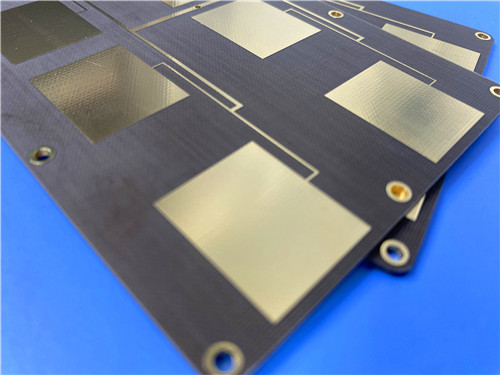
Today I'm showcasing a custom PCB built on Taconic TLX-8—a PTFE fiberglass laminate designed for reliability in a wide range of RF applications.
This custom PCB was fabricated using Taconic TLX-8, a high-volume antenna material with a dielectric constant of 2.55 and a dissipation factor of 0.0018 at 10 GHz. Its excellent PIM performance (below -160 dBc), dimensional stability, and low moisture absorption make it ideal for radar systems, mobile communications, and microwave test equipment.
Key Takeaways
- Material: Taconic TLX-8 — PTFE fiberglass laminate
- Key Benefit: Excellent PIM values (< -160 dBc), tightly controlled Dk (2.55 ± 0.04), dimensional stability
- Board Size: 45mm x 66.04mm | Thickness: 1.3mm
- Construction: Double-sided, no solder mask was applied on either side, no silkscreen was used
- Design: 13 components, 8 vias, 2 nets — a focused RF circuit
- Quality: IPC-Class-2 was met, and 100% electrical testing was performed
- The Challenge: Reliable Performance in Demanding RF Environments
An RF board was required by our customer that could deliver consistent performance across a range of environmental conditions. Tight dielectric constant control, low signal loss, and excellent PIM performance were essential. The design also needed to withstand the mechanical and thermal stresses typical of radar, communications, and test equipment applications.
TLX-8 was selected, a PTFE fiberglass laminate from Taconic's high-volume antenna material series. Here's why it was chosen:
Tightly Controlled Dk (2.55 ± 0.04 at 10 GHz)
Precise dielectric constant control was achieved, ensuring predictable impedance and consistent electrical performance across the board.
Low Dissipation Factor (0.0018 at 10 GHz)
Minimal signal loss was ensured, making this material suitable for sensitive microwave circuits.
Excellent PIM Performance
PIM values measured below -160 dBc were achieved—a critical requirement for communication systems where intermodulation distortion must be minimized.
Dimensional Stability
Excellent stability was demonstrated through bake and thermal stress testing, with minimal movement in both machine and cross directions.
Low Moisture Absorption (0.02%)
Minimal moisture absorption was ensured, preventing performance drift in humid environments.
High Dielectric Breakdown (> 45 kV)
Excellent insulation performance was provided for high-voltage applications.
UL 94 V-0 Rating
Flame resistance was confirmed for safety-critical applications.
Board Specifications
| Feature |
Specification |
| Dimensions |
45mm x 66.04mm (±0.15mm) |
| Stackup |
35μm Cu / 1.27mm TLX-8 / 35μm Cu |
| Finished Thickness |
1.3mm |
| Trace/Space |
6/9 mils |
| Min Hole Size |
0.4mm |
| Surface Finish |
ENIG |
| Solder Mask |
None (both sides) |
| Silkscreen |
None |
| Testing |
100% electrical |
| Standard |
IPC-Class-2 |
Design Statistics
| Metric |
Value |
| Components |
13 |
| Total Pads |
26 (12 through-hole, 14 SMT) |
| Vias |
8 |
| Nets |
2 |
The 2-net design with a modest via count indicates a focused RF sub-circuit—likely a filter, coupler, or amplifier stage. The balanced mix of through-hole and SMT components provides both mechanical strength and compact routing.
Electrical Properties
| Property |
Value |
Test Method |
| Dk @ 10 GHz |
2.55 ± 0.04 |
IPC-650 2.5.5.3 |
| Df @ 10 GHz |
0.0018 |
IPC-650 2.5.5.5.1 |
| Surface Resistivity (Elevated Temp) |
6.605 x 10^8 Mohm |
IPC-650 2.5.17.1 |
| Surface Resistivity (Humidity Cond) |
3.550 x 10^6 Mohm |
IPC-650 2.5.17.1 |
| Volume Resistivity (Elevated Temp) |
1.110 x 10^10 Mohm/cm |
IPC-650 2.5.17.1 |
| Volume Resistivity (Humidity Cond) |
1.046 x 10^10 Mohm/cm |
IPC-650 2.5.17.1 |
Dimensional Stability
| Property |
Value |
Test Method |
| MD After Bake |
0.06 mm/M |
IPC-650 2.4.39 Sec. 5.4 |
| CD After Bake |
0.08 mm/M |
IPC-650 2.4.39 Sec. 5.4 |
| MD Thermal Stress |
0.09 mm/M |
IPC-650 2.4.39 Sec. 5.5 |
| CD Thermal Stress |
0.10 mm/M |
IPC-650 2.4.39 Sec. 5.5 |
Coefficient of Thermal Expansion (25–260°C)
| Axis |
Value |
Test Method |
| X |
21 ppm/°C |
IPC-650 2.4.41 |
| Y |
23 ppm/°C |
IPC-650 2.4.41 |
| Z |
215 ppm/°C |
IPC-650 2.4.41 |
Thermal Decomposition
| Property |
Value |
Test Method |
| Td (2% Weight Loss) |
535°C |
IPC-650 2.4.24.6 |
| Td (5% Weight Loss) |
553°C |
IPC-650 2.4.24.6 |
Chemical / Physical Properties
| Property |
Value |
Test Method |
| Moisture Absorption |
0.02% |
IPC-650 2.6.2.1 |
| Dielectric Breakdown |
> 45 kV |
IPC-650 2.5.6 |
| Flammability Rating |
V-0 |
UL-94 |
Why This Matters: TLX-8 offers tightly controlled electrical properties, excellent dimensional stability, and high thermal decomposition temperatures—making it ideal for demanding RF and microwave applications.
Ideal Applications
Radar systems requiring reliable performance
Mobile communications infrastructure
Microwave test equipment
Microwave transmission devices
Couplers, splitters, combiners, amplifiers, and antennas
Q: What makes TLX-8 suitable for high-reliability applications?
A: Tightly controlled Dk, low moisture absorption, excellent dimensional stability, and a high dielectric breakdown voltage are all provided by TLX-8.
Q: What is PIM and why does it matter?
A: Passive Intermodulation (PIM) is distortion generated by non-linearities in passive components. Low PIM (< -160 dBc) is critical for communication systems to prevent interference.
Q: Why was no solder mask applied?
A: Solder mask introduces dielectric loss and impedance variation at high frequencies. By removing it, the purest possible RF signal path is ensured.
Q: What is the significance of the dimensional stability data?
A: Minimal movement during bake and thermal stress testing is demonstrated, ensuring that circuit dimensions remain stable through manufacturing and operation.
Q: How does TLX-8 handle high temperatures?
A: Thermal decomposition temperatures of 535°C (2% weight loss) and 553°C (5% weight loss) are withstood, making it suitable for demanding thermal environments.
Q: Is this material suitable for space applications?
A: Yes. The low outgassing and radiation resistance make TLX-8 an excellent choice for space and aerospace environments.
Final Thoughts
Taconic TLX-8 delivers tightly controlled electrical properties, excellent dimensional stability, and reliable performance in demanding environments. When your RF design requires consistent performance and long-term reliability, this material delivers.
Got a radar or microwave project in mind? I'd love to hear about it.


 Por favor verifique seu email!